- Proudly Made in the USA

Why Are Grounding Kits Essential for Global Buyers?
Grounding Kits are small components with serious safety responsibilities. They connect electrical equipment, structures, or cable systems to an intentional earth path. This path helps control fault current, static buildup, and transient overvoltage. The World Meteorological Organization reports approximately 24,000 lightning deaths and 240,000 injuries worldwide each year. Grounding cannot eliminate lightning risk. It can, however, support safer current dissipation when systems are correctly designed.
Global buyers face more than a simple product comparison. IEC 60364-4-41 emphasizes protection against electric shock through automatic supply disconnection and protective earthing. NFPA 70, the National Electrical Code, also defines requirements for grounding and bonding in many installations. IEEE Std 80 provides engineering guidance for grounding substations and managing touch and step potentials. These references show why kit selection must consider fault levels, soil resistivity, conductor material, corrosion exposure, and local installation rules.
Details matter. A copper lug may look suitable, yet its plating, hole size, and pressure rating can determine long-term performance. Stainless steel hardware may suit coastal facilities better than untreated carbon steel. Buyers should request test reports, material certificates, installation instructions, and evidence of compatibility with the target standard. UL 467 is often relevant for grounding and bonding equipment in North American projects, while IEC-based markets may require different verification routes. Certification alone is not a complete answer. That is the uncomfortable part. A compliant kit can still fail when installed loosely, buried in unsuitable soil, or paired with incompatible metals. Experienced procurement teams therefore evaluate the complete grounding design, not only the package label.
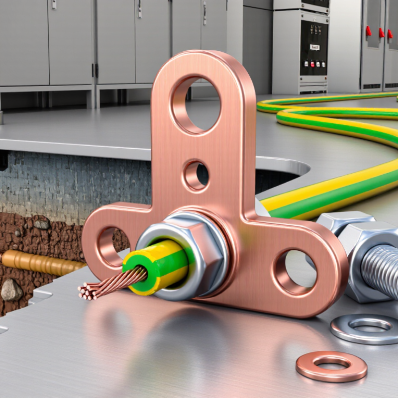
Grounding kits are practical sets of conductors, clamps, rods, connectors, and protective hardware. They connect electrical equipment to the earth. The goal is simple: provide a controlled path for unwanted current.
When a fault occurs, current travels through this path instead of remaining on exposed metal surfaces. This reduces shock risks and helps protective devices operate quickly. A grounding kit may also limit damage from surges and unstable electrical conditions. However, performance depends on correct installation. Soil moisture, corrosion, conductor length, and connection quality all matter. A kit can look complete, yet still fail because one connection was overlooked. That detail is easy to underestimate.
For global buyers, check material specifications, conductor sizes, and testing documents before purchase. Copper, galvanized steel, and stainless steel perform differently in wet or salty environments. Installation drawings should match the equipment and site conditions. Local electrical requirements may also affect rod depth, spacing, and inspection procedures. A qualified installer should measure soil resistance after installation. Do not assume the same kit suits every country or building. Field conditions often change the result.
Tips: Confirm compatibility with the site’s voltage and soil conditions. Inspect clamps for tight, clean contact. Keep records of resistance measurements and maintenance checks. Review the design when the site expands or equipment changes. Small gaps in planning can create serious grounding problems.

Grounding kits protect people, equipment, and electrical systems during fault conditions. They create a controlled path for unwanted current to reach the earth. This reduces touch voltage near metal enclosures, cable trays, and support structures. When insulation fails, the grounding path helps protective devices respond faster. Without this path, exposed metal may become dangerously energized. This risk is often invisible.
In practical electrical inspections, technicians examine clamps, conductors, bonding points, and earth electrodes. They check for loose connections, corrosion, mechanical damage, and unsuitable materials. Soil moisture and local climate also affect grounding performance. A dry site can produce different results from a wet industrial area. Small installation details matter. A loose clamp can defeat a complete kit.
Global buyers should request clear specifications, testing information, and installation guidance. Documentation should identify conductor sizes, compatible materials, environmental limits, and recommended inspection intervals. Products should support recognized electrical safety practices in the destination market. A kit may appear compliant on paper yet fail after poor installation. That assumption needs challenging. Buyers should evaluate the whole grounding path, not only the packaged components. Real safety depends on design, installation, testing, and maintenance working together.
Grounding kits provide a controlled path for fault current, helping protective devices disconnect power quickly and reducing shock, fire, and equipment-damage risks. The chart shows copper equipment grounding conductor sizes specified by NEC 2023 Table 250.122 for common overcurrent device ratings.
These values are minimum copper conductor sizes before any required adjustment for increased phase-conductor sizes. Local electrical codes, installation conditions, fault-current levels, and system type must always be verified before selecting a grounding kit.
Why Are Grounding Kits Essential for Global Buyers?
Key Components Found in a Grounding Kit
A reliable grounding kit begins with a conductor, usually copper or tinned copper, sized for fault current and environmental exposure. Clamps, lugs, bonding jumpers, and corrosion-resistant fasteners create the electrical path. An enclosure or earth bar organizes connections and supports inspection. These parts are not interchangeable decorations. IEC 60364-5-54 emphasizes protective bonding and earthing arrangements for low-voltage installations. NFPA 70 also requires effective grounding and bonding in applicable systems.
Field inspection experience shows that small details cause large failures. A loose lug can create heat. Unsealed metal can corrode quietly. The U.S. Bureau of Labor Statistics recorded 126 workplace electrical fatalities in 2020, showing why connection quality deserves attention. Market reports also forecast continued growth in grounding equipment demand as renewable energy and industrial infrastructure expand. Yet forecasts are not field proof. Product selection still needs testing, documentation, and site judgment.
Tips: Check conductor size, alloy compatibility, fault-current ratings, and torque values. Ask for test certificates and installation instructions. Confirm the kit meets local standards before shipment. A kit can look complete and still be wrong. Even experienced buyers may overlook galvanic corrosion between dissimilar metals. Review the soil, moisture, vibration, and maintenance access before approving the final configuration.
Grounding requirements differ because electrical systems, soil conditions, and safety rules vary by country. IEC 60364 uses TN, TT, and IT arrangements, each requiring different fault-current paths and protective measures. In the United States, NFPA 70 Article 250 addresses grounding electrodes, bonding, and conductor sizing. Australia and New Zealand apply AS/NZS 3000, while China follows related GB/T requirements. A kit suitable for one market may fail inspection in another.
The International Energy Agency’s Electricity 2024 report projects global electricity demand to grow by an average 3.4% annually through 2026. More power equipment means more exposed metalwork, cable trays, inverters, and enclosures requiring reliable bonding. Buyers should check voltage, prospective fault current, electrode design, corrosion exposure, and local certification. A green-yellow conductor alone is not a complete grounding solution. That assumption is still common—and risky.
Tips:
Request the destination country’s wiring standard before ordering. Confirm conductor material, cross-sectional area, connector torque, and enclosure compatibility. Ask for test records, installation drawings, and corrosion data. For solar or outdoor systems, verify lightning-protection coordination separately. Documentation matters. Even experienced teams can miss a small regional requirement.
Choosing the right grounding kit starts with the site, not the product photo. Global buyers should check soil type, moisture, climate, and installation depth. Rocky ground may need a different electrode design than wet clay. Coastal locations also demand stronger corrosion protection. Small details matter.
Review the kit’s conductor size, clamp material, rod length, and connection method. Copper, copper-bonded steel, and galvanized components perform differently in various environments. Ask for material certificates, test reports, and clear installation instructions. Confirm that the kit matches the equipment’s voltage, current, and connection points. Local electrical requirements should guide the final choice.
A practical buyer should also examine packaging and delivery conditions. Damp storage can damage connections before installation. I once focused too heavily on price and overlooked the cost of extra drilling equipment. That was a poor assumption. A complete kit may reduce labor, but only when its parts fit the site correctly. Ask whether replacement clamps and inspection points are available. After installation, measure grounding resistance with suitable testing equipment and keep the result on record. The lowest quoted price is not always the most reliable option. Sometimes, a slightly higher initial cost prevents repeated maintenance later.
| Selection Dimension | What to Check | Typical Technical Reference | Why It Matters to Global Buyers | Recommended Buying Decision |
|---|---|---|---|---|
| Electrical Safety Function | Confirm that the kit provides a reliable low-impedance path for fault current and helps reduce dangerous touch and step voltages. | System design should follow the applicable electrical code and the equipment manufacturer's grounding requirements. | Correct grounding helps protective devices operate during faults and reduces electric-shock risk. | Choose a complete kit designed for the intended voltage system, equipment type, and installation environment. |
| Applicable Standards | Review the standards required in the destination market, project specification, and industry sector. | Common references include IEC 60364, IEC 62305, IEEE 80, NFPA 70, UL 467, and local electrical regulations. Requirements vary by application and country. | Standards affect conductor sizing, electrode selection, bonding, testing, documentation, and product acceptance. | Request compliance documents and have the design checked by a qualified local electrical professional. |
| Conductor Material | Evaluate conductivity, corrosion resistance, mechanical strength, and compatibility with connected metals. | Common options include bare copper, tinned copper, copper-clad steel, galvanized steel, and stainless steel. | Material selection influences service life, installation cost, theft exposure, and performance in corrosive soil. | Use copper-based conductors for many general installations; consider galvanized or stainless steel where soil chemistry or mechanical conditions require it. |
| Conductor Cross-Section | Check the required size for fault current, clearing time, mechanical protection, and local code requirements. | Typical earthing conductors may range from 6 mm² to 70 mm² or more, but the correct size must be calculated for each installation. | Oversized or undersized conductors can increase cost or fail to provide adequate fault-current capacity. | Do not select by appearance alone; require a calculation or code-based sizing recommendation. |
| Grounding Electrode Type | Compare rods, plates, grids, tapes, rings, and foundation or structural electrodes. | Common rod lengths include approximately 1.2 m to 3 m; diameter, spacing, and depth depend on soil and design requirements. | Electrode geometry and installation depth strongly affect resistance and long-term stability. | Select the electrode arrangement according to measured soil resistivity, available space, and local regulations. |
| Soil and Corrosion Conditions | Assess moisture, salinity, acidity, temperature, drainage, and contact between dissimilar metals. | Soil resistivity is commonly measured in ohm-metres; lower resistivity generally supports easier dissipation of fault current. | Highly corrosive or dry soil may shorten service life and increase the required number or length of electrodes. | Obtain a soil assessment for critical projects and select compatible materials, coatings, or corrosion-protection measures. |
| Connection Method | Inspect clamps, lugs, bonding bars, exothermic connections, bolts, washers, and protective coatings. | Connections should be mechanically secure, electrically continuous, accessible for inspection where required, and protected against corrosion. | A poor joint can create a high-resistance point even when the conductor and electrode are correctly sized. | Prefer connection hardware rated for the conductor material, environment, and expected fault current. |
| Lightning Protection Compatibility | Determine whether the kit will be connected to a lightning protection system or surge protection arrangement. | Lightning protection design commonly references IEC 62305 and requires coordinated bonding and down-conductor arrangements. | Grounding alone does not replace a complete lightning protection system; coordination helps control transient currents. | Use a dedicated lightning protection design when the building, structure, or risk assessment requires it. |
| Installation Environment | Consider indoor or outdoor use, direct burial, concrete embedding, vibration, UV exposure, flooding, and temperature. | Outdoor and buried components should be suitable for moisture, ultraviolet exposure, soil contact, and expected temperature conditions. | Environmental mismatch can cause insulation damage, corrosion, loose connections, or premature maintenance. | Specify the installation environment before requesting quotations and technical drawings. |
| Testing and Verification | Confirm continuity testing, earth resistance testing, inspection access, and commissioning records. | Fall-of-potential, clamp-based, or other approved test methods may be used depending on the grounding system and site conditions. | Testing verifies that the installed system performs as designed rather than relying only on product documentation. | Require a test plan, acceptance criteria, and final measurement report for commercial and industrial projects. |
| Kit Completeness | Check whether the package includes electrodes, conductors, clamps, lugs, bonding hardware, warning labels, and installation instructions. | A kit should list each component, material, quantity, dimensions, and applicable technical specification. | Missing accessories can delay installation, create compatibility issues, and increase landed cost. | Compare complete bills of materials instead of comparing only the price of the main electrode or cable. |
| International Logistics | Review product dimensions, shipping weight, packaging protection, customs documentation, and replacement-part availability. | Long electrodes and metal assemblies may require special packing or transport arrangements; documentation should match the shipment. | Packaging and paperwork affect delivery time, import clearance, damage rates, and total procurement cost. | Request carton dimensions, packing lists, material declarations, and installation documents before placing an international order. |
| Maintenance Requirements | Identify inspection intervals, tightening requirements, corrosion checks, test-point access, and replacement procedures. | Inspection frequency should follow local codes, risk level, environmental exposure, and the facility maintenance plan. | Low-maintenance systems can reduce lifecycle costs and help maintain safety performance over time. | Select a design with accessible test points and clear maintenance instructions. |
| Supplier Documentation | Request drawings, datasheets, material certificates, test reports, installation instructions, and traceability records. | Documentation should identify dimensions, materials, tolerances, ratings, test methods, and revision status. | Clear documentation supports engineering approval, import compliance, installation quality, and future maintenance. | Approve only after technical and document review |
| Total Cost of Ownership | Compare purchase price with freight, installation labor, testing, corrosion protection, maintenance, and replacement costs. | Lifecycle cost is more meaningful than unit price for systems expected to remain in service for many years. | The lowest initial price may lead to higher costs if the kit is difficult to install, frequently corrodes, or lacks documentation. | Choose the technically compliant option with the best balance of service life, installation effort, and verified performance. |
Whether you’re looking for fire-rated walls, doors, openings, floors or a specialty service, we have the solution for you. With over 40 years of experience in testing, innovating, and providing technologically advanced fire-rated glass and framing products, we deliver unyielding performance and quality at a competitive price.
