- Proudly Made in the USA
What Is a butterfly valve and How Does It Work? This guide examines the compact device behind many water, air, chemical, and process-control systems. A butterfly valve uses a circular disc mounted on a rotating shaft. The disc turns inside the pipe. A quarter-turn usually moves it from fully open to fully closed. Simple movement. Serious engineering.
Greg Johnson, a longtime valve-industry educator, states, “Valve selection begins with the process, not the product name.” That principle deserves attention. Pipe size alone cannot determine the correct butterfly valve. Engineers must consider pressure, temperature, fluid composition, flow speed, seat material, and operating frequency. A rubber-lined valve may perform well in clean water. It may struggle with abrasive slurry or aggressive chemicals. The same design can behave differently across two nearby facilities.
When the handle or actuator rotates the shaft, the disc changes the available flow area. In the open position, the disc aligns with the fluid path. In the closed position, it blocks the passage and presses against the seat. Lug, wafer, and double-flanged bodies suit different installation needs. Electric and pneumatic actuators support remote control. Manual handles remain useful for smaller lines.
The explanation can sound too neat. Real systems are less forgiving. Incorrect alignment can damage the seat. Excessive throttling may create turbulence, noise, or premature wear. Even a dependable butterfly valve needs inspection, correct torque, and suitable materials. This article explores its parts, operating principle, advantages, limitations, and practical selection criteria. It also questions where this valve works well—and where another design deserves a closer look.
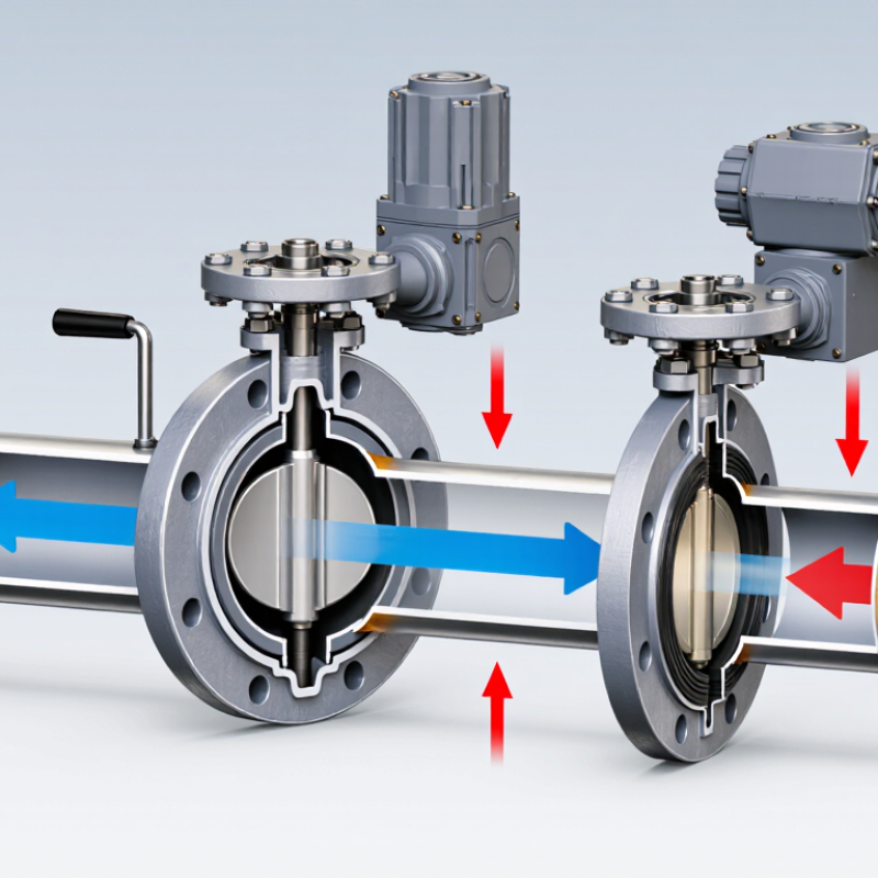
A butterfly valve is a quarter-turn device used to start, stop, or regulate fluid flow. Its main part is a circular disc mounted inside a pipe. A stem connects the disc to a handle or actuator. When the stem turns, the disc rotates around its central axis.
The basic design is compact and relatively light. The valve body fits between pipe flanges, while a resilient seat surrounds the disc and limits leakage. With the disc aligned with the pipe, fluid passes through the opening. A 90-degree turn places the disc across the passage and stops most flow. This movement is quick and easy to observe during routine maintenance.
That simplicity can mislead.
In field inspections, a valve may look closed while the disc remains slightly misaligned. Sediment, worn seats, or incorrect installation can affect sealing performance. Operators should check the flow direction, flange alignment, stem movement, and actuator settings. Material selection also matters because temperature, pressure, and fluid chemistry influence service life. A valve suitable for clean water may perform poorly with abrasive slurry or corrosive chemicals.
Butterfly valves are often effective for isolation and moderate flow control, but they are not perfect throttling devices. At partial opening, the disc can create turbulence, vibration, and pressure loss. Engineers usually confirm the pressure rating and operating temperature before selection. The smallest detail matters. A damaged seat can turn a reliable design into a persistent leak.

A butterfly valve controls flow with a circular disc mounted inside a pipe. When the disc turns parallel to the flow, liquid or gas passes with limited resistance. Turning it across the passage blocks the route. Most designs use a quarter-turn movement, making operation quick. The body supports the pressure boundary and connects to the piping system. Its internal finish also matters because rough surfaces can disturb flow or collect deposits.
The disc is the main throttling element, while the stem transfers movement from the actuator to the disc. A resilient or metal seat creates the sealing line around the disc. Stem seals help prevent leakage into the surrounding area. The actuator may be a hand lever, gearbox, pneumatic unit, or electric unit. Each option requires suitable operating torque. A lever looks simple, but vibration can make the position indicator less reliable than expected. Small details matter here.
During inspection, technicians check the disc edge, seat condition, stem movement, and actuator response. They also verify pressure ratings and flange alignment before operation. Misalignment can increase friction and damage the seat. A valve may appear closed while a damaged seat still allows passage. This is an easy point to overlook. In real installations, no component works alone; pipe strain, dirt, temperature, and incorrect torque can all affect sealing performance. The design seems simple, but maintenance decisions still require careful judgment.
What Is a Butterfly Valve and How Does It Work?
A butterfly valve controls flow with a circular disc inside the pipe. Its operation is simple, but timing matters. When the actuator turns the stem, the disc rotates around its central axis. At 0 degrees, the disc aligns with the pipeline and allows near-full flow. As it turns toward 90 degrees, the disc blocks the passage. The seal then presses against the disc edge, limiting leakage. Operators may use a hand lever, gearbox, pneumatic actuator, or electric actuator. Each option changes response speed and maintenance needs.
During partial opening, flow strikes the disc and creates turbulence. This can increase noise, vibration, and pressure loss. A 2024 report from Fortune Business Insights valued the global industrial valve market at about USD 78.3 billion in 2023, showing the scale of systems that depend on reliable flow control. Yet market size does not guarantee correct selection. Disc material, seat design, pressure rating, and fluid temperature must match actual service conditions. Small errors become expensive quickly.
Tips: Confirm the valve’s pressure class before installation. Check the stem position visually. Exercise the valve periodically to prevent sticking. Do not assume a standard seat suits abrasive fluid. In field work, a partly open disc may look harmless, but it can wear quickly under high velocity. My practical view is cautious: butterfly valves are efficient isolators, but they are not always ideal for precise throttling. The correct answer depends on the whole piping system.
| Category | Data Dimension | Factual Description | Operating Significance |
|---|---|---|---|
| Basic Definition | Valve type | A butterfly valve is a quarter-turn rotary valve used to start, stop, or regulate fluid flow. | A 90-degree rotation moves the valve between its main open and closed positions. |
| Main closure element | A circular disc mounted inside the flow passage. | The disc changes the available flow area as it rotates. | |
| Typical movement | The disc rotates around a shaft or stem. | The movement is compact and requires less space than many multi-turn valve designs. | |
| Primary flow paths | The valve may be installed in liquid, gas, or slurry piping when the selected design is suitable for the service. | Media compatibility depends on the body, disc, shaft, seat, pressure, temperature, and fluid properties. | |
| Common body styles | Wafer, lug, flanged, and double-flanged configurations are commonly used. | The connection style determines how the valve is positioned and secured between or to pipe flanges. | |
| Control function | Butterfly valves can provide isolation or throttling, depending on their design and service requirements. | Frequent throttling should only be performed when the valve is rated for control duty. | |
| Sealing method | A resilient seat or a metal-seated arrangement forms the shutoff interface. | The seat material and design influence leakage performance, temperature capability, and chemical compatibility. | |
| Actuation options | Manual handles, gear operators, pneumatic actuators, electric actuators, and hydraulic actuators may be used. | The actuator must provide enough torque for the operating pressure, seat friction, and safety requirements. | |
| Operating Sequence | Step 1: Closed position | The disc is positioned across the pipe bore. | The disc and seat restrict the passage and provide shutoff when the valve is correctly selected and installed. |
| Step 2: Input from operator | A hand lever, gearbox, or actuator applies rotational force to the stem. | The applied torque overcomes resistance from the seat, disc, shaft, and differential pressure. | |
| Step 3: Stem rotation | The stem transfers the turning force to the disc. | The disc rotates about its shaft axis rather than moving linearly along the pipe. | |
| Step 4: Opening begins | As the disc turns away from the crosswise position, the flow area increases. | Fluid flow usually increases as the disc angle opens, although the relationship is not perfectly linear. | |
| Step 5: Intermediate position | The disc is partly rotated across the bore. | The partial opening creates a restriction and can be used for flow control when permitted by the valve design. | |
| Step 6: Fully open position | The disc is rotated approximately 90 degrees from the closed position and lies broadly parallel to the flow. | The passage is at or near its maximum effective area, minimizing the valve's flow restriction for that installation. | |
| Step 7: Closing | The actuator reverses the stem rotation until the disc returns to the seat. | The seat contacts the disc perimeter and limits or stops flow, subject to the valve's specified shutoff performance. | |
| Performance Factors | Pressure drop | The disc remains in the flow path even when open. | This can create more pressure loss than a full-bore valve with an unobstructed passage. |
| Flow control behavior | Flow changes with disc angle, pressure differential, and fluid properties. | A valve characteristic curve should be used when accurate modulation is required. | |
| Torque requirement | Torque is affected by valve size, pressure differential, seat friction, temperature, and media. | Actuator sizing should use the manufacturer's certified torque data for the specific valve construction. | |
| Installation alignment | The disc needs adequate clearance inside the pipe and must not strike adjacent components. | Incorrect alignment can damage the disc or seat and may prevent full opening or closing. | |
| Temperature limit | The allowable temperature is determined largely by the seat, seals, body, and disc materials. | The published pressure-temperature rating must be checked before operation. | |
| Maintenance focus | Inspection commonly includes the seat, disc edge, shaft, actuator, fasteners, and external leakage points. | Periodic functional checks help confirm that the valve reaches both defined end positions. | |
| Safety requirement | The line should be isolated and depressurized before maintenance or disassembly. | Lockout and tagout procedures should be followed because stored pressure and automatic actuators can create hazards. |
A butterfly valve controls flow with a circular disc mounted on a rotating shaft. The disc turns inside the pipe, opening, throttling, or stopping media movement. A quarter-turn usually moves the valve from closed to open. Its compact body makes it useful where installation space is limited. During field checks, technicians often inspect disc clearance, shaft alignment, and seat condition before operation.
Common configurations include wafer, lug, and double-flanged designs. A wafer valve fits between two pipe flanges and suits many space-conscious installations. A lug valve has threaded inserts, allowing one pipe section to be removed while the opposite side remains secured. Double-flanged models use flanges on both ends and provide stronger support for larger or heavier piping. Each arrangement affects maintenance access and installation cost.
Butterfly valves also differ by seat and disc design. Resilient-seated valves offer reliable shutoff for water and many low-temperature services. High-performance valves often use an offset shaft, reducing seat friction during rotation. Metal-seated versions handle higher temperatures and abrasive conditions, but they may permit slight leakage. Manual levers work well for small valves, while gearboxes or actuators support larger sizes and remote control. The simple appearance can mislead. Incorrect seat material, pressure rating, or actuator sizing may cause early failure. A careful selection should consider fluid properties, temperature, pressure, pipe alignment, and the required control accuracy.
Butterfly valves are quarter-turn valves that regulate or isolate flow by rotating a disc around a central or offset shaft. The chart shows indicative pressure-rating bands commonly associated with major butterfly valve configurations.
Wafer and lug designs are commonly used in lower- to medium-pressure piping, while double-flanged and triple-offset designs are often selected for larger sizes, higher pressures, higher temperatures, or tighter shutoff requirements. Actual ratings depend on the applicable standard, body and seat materials, valve size, and operating temperature.
A butterfly valve controls flow with a circular disc mounted on a rotating stem. Turning the stem about a quarter turn moves the disc from open to closed. When the disc aligns with the pipe, fluid passes through with limited resistance. At a right angle, the disc blocks the passage. Operators commonly use these valves in water treatment, HVAC systems, irrigation lines, and industrial process piping.
Their compact body saves space between pipe flanges. They also weigh less than many gate or globe valves, which can simplify installation and maintenance. Quarter-turn operation supports quick shutoff during routine servicing. However, a butterfly valve is not automatically suitable for every application. Partial opening can create turbulence, vibration, and disc wear. Abrasive media may damage the sealing surface. High temperatures can also exceed the limits of the seat material. It depends on the design.
Tips: Check the medium, pressure, temperature, and pipe size before selection. During inspection, look for stem looseness, seat damage, and unusual operating torque. A valve that feels stiff may need attention, not force. For accurate control, confirm its tested flow characteristics rather than relying only on its compact appearance. In field work, small alignment errors can cause leakage. That detail is easy to underestimate.
Whether you’re looking for fire-rated walls, doors, openings, floors or a specialty service, we have the solution for you. With over 40 years of experience in testing, innovating, and providing technologically advanced fire-rated glass and framing products, we deliver unyielding performance and quality at a competitive price.
